Physical radio channel models
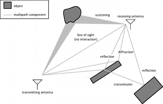
In propagation modelling, the wirelessly transmitted signal is assumed to arrive at the receiving antenna under the form of a collection of plane waves, also called propagation paths or multipath components. Each propagation path travels from transmitting antenna to receiving antenna while interacting with physical objects in the environment. In a realistic environment, due to a multitude of possible interacting objects, it is easy to comprehend that a multitude of possible propagation paths will arise. This phenomenon is called multipath propagation. Multipath propagation is schematically shown in Fig. 1.

Physical channel models describe wireless propagation in terms of parameters of propagation paths. Various parameters can be associated with a propagation path, among others:
- Directional parameters which describe the spatial properties of the propagation path. These parameters are the two angles at which a propagation path leaves the transmitting antenna and arrives at the receiving antenna. Each of these two angles is fully specified by its azimuth and elevation angle in a spherical coordinate system.
- A delay parameter which quantifies the amount of time it takes for a propagation path to travel from the transmitting to the receiving antenna.
- A complex amplitude parameter which expresses the magnitude and phase of the propagation path's electric or magnetic field as seen at the receiving antenna.
- ...
The different propagation path parameters can also be seen as multiple dimensions in propagation path parameter space; physical channel modelling is therefore also sometimes referred to as multidimensional channel modelling.
In the field of multidimensional channel modelling, WiCa does the following:
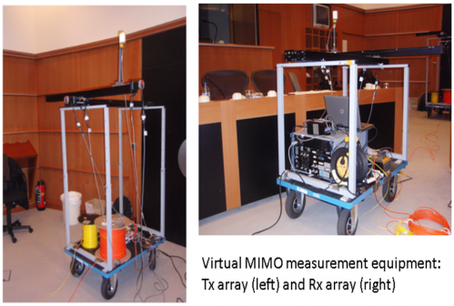
- Measurement campaigns in different environments (office, industrial, conference rooms,...) to capture the spatial, frequency, time, and polarization characteristics of the radio channel. For this, we use a measurement system consisting of virtual antenna arrays at both link ends and a vector network analyser to measure the complex channel gain (Fig. 2).

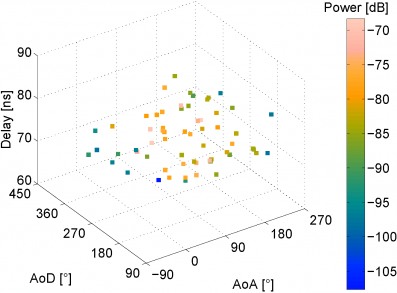
- Researching and applying algorithms for the extraction of propagation path parameters from measurement data (ESPRIT, SAGE, RiMAX,...). As an example, Fig. 3 shows a scatter plot of propagation path parameters (Azimuth of Arrival or AoA, Azimuth of Departure or AoD, Delay, and Power) obtained with ESPRIT from measurement data in an office environment.

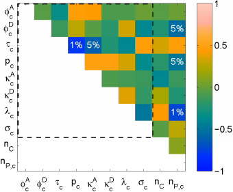
- Multivariate statistical modelling of the extracted propagation path parameters. For example, Fig. 4 shows a multivariate correlation analysis of distributional parameters associated with the statistical distributions of measured propagation path parameters.
